Posts

Showing posts from November, 2018

Week of 11-14-2018 to 11-21-2018

Image
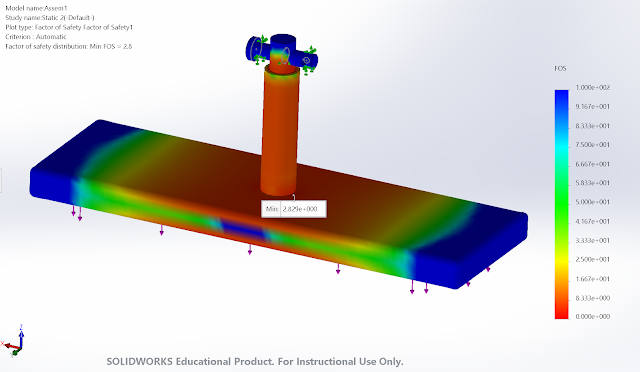
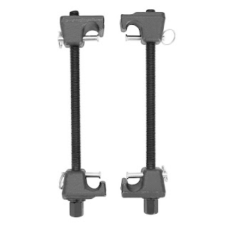
For this week, I was able to fully redesign the braking system. There were several issues from the last design such as twisting of the inside rod during braking and the ability to compress the spring back after system is deployed. The redesign fixes all of these issues. The rods that are protruding from the sides of the design are mounting spots for a spring compressor. There is also a notch in the bottom section of the rod with a pin inside the assembly. This will not allow the rod to rotate during deployment. FEA has been ran on the entire system and has a minimum factor of safety of 2.

Week of 11-07-2018 to 11-14-2018

Image
I have been focusing on my portion of the final report for this week. I have also designed and performed FEA on my lower armature assembly. I had to design a bracket because the previous weeks designed failed during FEA. I am currently remodeling my design to include a way to compress the spring and to prevent the rod from turning inside of slider assembly. Below is an FEA result for my bracket and armature assembly. I got a FOS of 1.7.

Week of 10-31-2018 to 11-07-2018

Image
Emergency Brakes: For this week, I ran FEA on the armature assembly to make sure that It can withstand forces that that will be present. A force of 1500lbf was applied to the bottom of the armature which simulates the pulling force of the electromagnet. The minimum factor is 2.8 which is acceptable. Furthermore, the Von-Mises effective stress is below the yield strength of the material which is also good. I will continue to run FEA on other parts as well.

Week of 10-24-2018 to 10-31-2018

Image
Emergency Braking System Improvements There were several problems that were solved this week regarding the emergency braking system. The problems included: Compressing 1500 lbf spring after the brakes are deployed.  Alignment issues with electromagnet Maintainability (inspection)  Main rod is able to rotate A simple solution was found to compress the spring after it has been deployed. Auto mechanics use a tool called a spring compressor which is able to compress springs to change dampers. This tool is show below in Figure 1. This tool is extremely strong and will be able to compress the spring that has been selected for our system. The system will need some simple modifications to accommodate the spring compressor.  Figure 1.  The spring compressors feature a long threaded bolt which will compress the springs when rotated with a 19mm socket. The top and bottom U shaped pieces will attach to the assembly to compress the spring.  The electromagnet needs to have pe