Week of 10-24-2018 to 10-31-2018
Emergency Braking System Improvements
There were several problems that were solved this week regarding the emergency braking system. The problems included:


There were several problems that were solved this week regarding the emergency braking system. The problems included:
- Compressing 1500 lbf spring after the brakes are deployed.
- Alignment issues with electromagnet
- Maintainability (inspection)
- Main rod is able to rotate
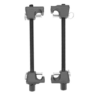
A simple solution was found to compress the spring after it has been deployed. Auto mechanics use a tool called a spring compressor which is able to compress springs to change dampers. This tool is show below in Figure 1. This tool is extremely strong and will be able to compress the spring that has been selected for our system. The system will need some simple modifications to accommodate the spring compressor.

Figure 1.
The spring compressors feature a long threaded bolt which will compress the springs when rotated with a 19mm socket. The top and bottom U shaped pieces will attach to the assembly to compress the spring.
The electromagnet needs to have perfect alignment so that the armature will stick to it when powered on. If the armature is off alignment, the magnet will not be able to hold it. With the previous design, the armature and rod are welded together. This may cause issues when aligning the armature after the system has been deployed. Maintainability also needs to be addressed. The current design is completed welded together and cannot be taken apart. The system will probably never need to be taken apart, but it is always good to have some freedom if problems occur or if needs to be inspected. Figures 2 and 3 below shows the modified armature and rod. The armature will now have the ability to detach from the main rod that connects up to the brake pad.

Figure 2.

Figure 3.
Furthermore, the introduction of this design will also solve alignment issues. After the system has been deployed, the spring will be compressed and the clevis pin will be removed to disconnect armature from main rod. Then the armature will be placed placed on the magnet. The magnet will be turned, which will hold the armature. The two rod pieces will be connected using the clevis pin show above. The spring compressors will be removed and system is now in operation.
The main rod is able to rotate inside the assembly and this can cause major issues. When the system is deployed, the main rod may rotate which will cause the brake pad to rotate. The fix this issue, 2-3 inches of the rod will have a keyway. A bolt will be screwed from the outside of the slider that will go into the keyway. This will prevent the rod from rotating. I hope to have the CAD of this shortly, hopefully next week.


Comments
Post a Comment